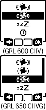
Automatic Levelling
After switching on, the measuring tool checks the horizontal and vertical position and automatically levels out any unevenness within the self-levelling range of approx. ±8.5 % (±5°).
The symbol for levelling flashes on the display during levelling. The status indicator (12) on the measuring tool and the status indicator for the respective axis ((34) or (33)) on the remote control flash green at the same time.
The rotation is stopped until levelling has been completed and the laser beams are flashing. The start screen will appear after levelling has been successfully completed. The laser beams will light up continuously and rotation will start. The status indicator (12) on the measuring tool and the status indicator for the levelled axis ((34) or (33)) on the remote control will light up green continuously.

If the measuring tool is at a slant of more than 8.5 % or is positioned differently to the horizontal or vertical position, levelling will no longer be possible. An error message will appear on the display and the status indicator (12) will flash red.
Reposition the measuring tool and wait for it to re-level.

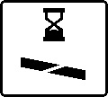
If the maximum levelling time is exceeded, levelling will be discontinued with an error message.
Reposition the measuring tool and briefly press the on/off button (11) to restart levelling.
When the measuring tool is levelled in, it continuously checks the horizontal and vertical position. Re-levelling is automatically performed if there are any position changes.
Minimal position changes are levelled out without interrupting the operation. This automatically compensates subsoil ground vibrations or weather influences.
For larger position changes, the rotation of the laser beam will be stopped in order to avoid faulty measurements during the levelling process and the laser beams will flash. The levelling symbol appears on the display. The shock-warning function will be actuated, if required.
The measuring tool will automatically detect the horizontal or vertical position. To change between the horizontal and the vertical position, switch the measuring tool off, reposition it and switch it on again.
If the position is changed without switching on/off, an error message will appear and the status indicator (12) will flash red quickly. Briefly press the on/off button (11) to restart levelling.
The measuring tool has a shock-warning function. After position changes or shock to the measuring tool, or in case of ground vibrations, it keeps the measuring tool from levelling in at changed positions, and thus prevents errors caused by a change in the measuring tool's position.
GRL 650 CHVG: The shock-warning function operates at two sensitivity levels. After the measuring tool is switched on, the setting defaults to high sensitivity.
To activate shock warning:
The shock-warning function is switched on by default. It is activated approximately 30 s after the measuring tool has been switched on.
During activation, the shock-warning function indicator (c) will flash on the display. The indicator lights up continuously after activation.
Shock warning actuated:
If the position of the measuring tool is changed or a severe knock is registered, the shock warning will be actuated. The laser will stop rotating and an error message will appear. The status indicator (12) will quickly flash red and a warning signal will sound at a fast rate.
Confirm the warning message with  by pressing the slope button (14) on the measuring tool or the slope button (31) on the remote control. When working with automatic levelling (including slope operation), levelling is automatically restarted.
Now check the position of the laser beam at a reference point and, if necessary, correct the height or alignment of the measuring tool.
To adjust/switch off the shock-warning function:
On the start screen, the current setting is shown with the shock-warning indicator (c):

Shock-warning function is switched on at high sensitivity.

GRL 650 CHVG: Shock-warning function is switched on at reduced sensitivity.

Shock-warning function is switched off.
Briefly press the on/off button (11) to adjust the shock-warning function setting. Then press the on/off button (11) in the menu which subsequently appears as many times as needed until the required setting has been selected. Confirm your selection with by pressing the slope button (14).
If the shock-warning function has been switched on, it will be activated after approximately 30 seconds.
In the measuring tool's horizontal position, the X-axis and the Y-axis can be tilted independently of each other in a range of ±8.5%.
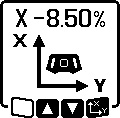
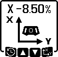
To tilt the X-axis, press the slope button (14) on the measuring tool or the slope button (31) on the remote control once. The menu for setting the slope of the X-axis will appear.
Set the required slope by using the buttons ▲ (4) or ▼ (3) on the measuring tool or using the up (30) or down (35) slope buttons on the remote control. Pressing both slope buttons on the measuring tool or on the remote control at the same time resets the slope back to 0.00%.
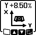
To tilt the Y‑axis, press the slope button (14) on the measuring tool or the slope button (31) on the remote control again. The menu for setting the slope of the Y-axis will appear.
Set the required slope in the same way as outlined for the X‑axis.
The selected slope is implemented on the measuring tool a few seconds after the last press of a button. Both the laser beam and the symbol for setting the slope on the display will flash until the process of setting the slope has been completed.
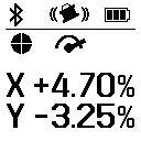
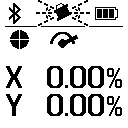
After the process of setting the slope has been completed, the set slope values of both axes will be shown on the start screen. The status indicator (12) on the measuring tool will light up red continuously. On the remote control, the status indicator for the tilted axis ((34) and/or (33)) will light up red continuously.
The measuring tool saves the four most recently used slope values of both axes. As an alternative when readjusting the slopes, you can apply these saved slope combinations.
Start the slope operation for the X‑axis see Slope operation in the horizontal position.
To call up the slope memory, press the line operation button (5) on the measuring tool or the line operation button (28) on the remote control.
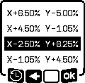
To select one of the four saved combinations, press the line operation button (5) on the measuring tool or the line operation button (28) on the remote control as many times as needed until the required combination is indicated on the display.
Confirm the selection by pressing the slope button (14) on the measuring tool () or the slope button (31) on the remote control. The slope combination is implemented on the measuring tool a few seconds after the button is pressed see Slope operation in the horizontal position.
To set a value other than one of those saved, press the ▲ button (4) on the measuring tool ( ) or the slope up button (30) on the remote control. The indicator returns to the slope operation settings menu see Slope operation in the horizontal position.
Temperature changes in the measuring tool can have effects on the set slope of the axes.
To avoid measurement inaccuracies, the slope of the axes is readjusted when exceeding the set temperature difference. The measuring tool is levelled in, then it returns to slope operation with the previously set values.
The slope is reset at temperature changes of ≥5 °C.
GRL 650 CHVG: Using the Bosch Levelling Remote App, the temperature difference can be lowered to 2 °C or the SlopeProtect function can be switched off altogether. This setting is not saved when the measuring tool is switched off.