Symbols
The following symbols may be important for the operation of your power tool. Please take note of these symbols and their meaning. Correctly interpreting the symbols will help you to operate the power tool more effectively and safely.
Symbols and their meaning | |
|---|---|
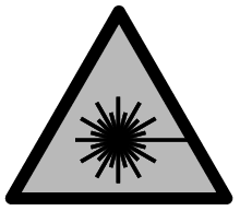
| CLASS 1 LASER PRODUCT |
| Keep hands away from the cutting area while the power tool is running. Contact with the saw blade can lead to injuries. |
| Wear a dust mask. |
| Wear safety goggles. |
| Wear hearing protection. Exposure to noise can cause hearing loss. |
| Danger area! Keep hands, fingers and arms away from this area. |
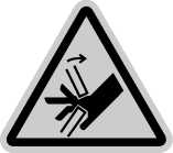
| Keep your fingers away from the moving parts of the glide arm. There is a risk of fingers being crushed and severely injured. |
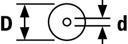
| Take note of the dimensions of the saw blade (saw blade diameter D, hole diameter d). The hole diameter d must match the tool spindle without play. If it is necessary to use reducers, ensure that the dimensions of the reducer are suitable for the base blade thickness and the saw blade hole diameter, as well as the tool spindle diameter. Wherever possible, use the reducers provided with the saw blade. The saw blade diameter D must match the information specified on the symbol. See also: "Dimensions of suitable saw blades" in the "Technical Data" section. |
| When transporting the power tool, hold it only at the locations indicated (recessed handles) or by the transport handle. |
| Never carry the power tool using the handle of the glide arm. |
| Switching on the laser |
| Clamping handle open: Adjusting bevel angles is possible. Clamping handle closed: The set bevel angle of the glide arm is locked. |
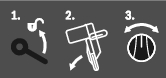
| Indicates the individual steps for adjusting the bevel angle. |
| Setting the bevel angle ranges using the rotary knob: |
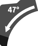
| Saw blade inclination to the left (45° to 0°) |
| Saw blade inclination to the right (0° to 45°) |
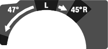
| Entire swivel range of the glide arm (-47° to +47°) |